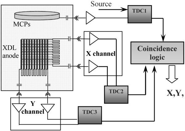
Fig. 1.

Schematic diagram of previous data processing system for cross delay line detector, which uses 3 time-to-digital converter (TDC) units to provide 2 dimensional position of an event and its timing. The 3 TDC units have to be synchronized through coincidence logic to appropriately match data flows. The timing channel uses the pulse at the back electrode of the MCP stack occurring at the moment when the electron cloud leaves the MCP.
