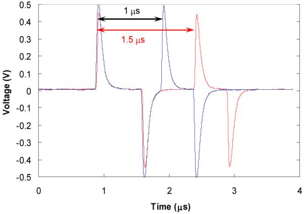
Fig. 6.

Two input pulses used in calibration of timing resolution. The two pulses separated by 1 and 1.5 μs stimulated the readout electronics to simulate the signals produced by two events separated by a well known time interval. The graphs shows the pulses measured with 500 MHz digital scope. Square pulses generated by a SRS DG535 pulse generator were AC coupled into electrodes of the preamplifier board, resulting in the differential signals shown above, with the positive signals used for the timing experiments.
