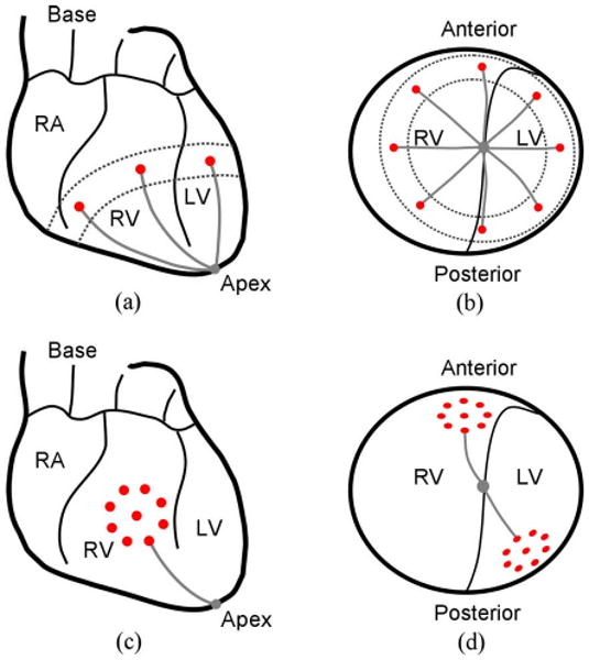
Fig. 3.

(a) Anterior view and (b) apex view of the navigation task. The targets are shown by the dark circles and the paths by the gray lines. The circumference of the ventricles is the region between the broken lines. (c) Anterior view of the positioning task. (d) Apex view of the positioning task.
