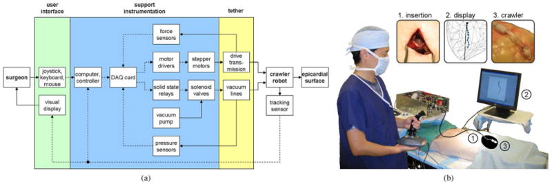
Fig. 4.

(a) Schematic diagram of the HeartLander system, which comprises the user interface, the support instrumentation, and the tethered crawling robot. Mechanical flow is indicated by solid lines, while data flow is shown by broken lines. (b) Operating room during in vivo animal testing, showing the surgeon interacting with the HeartLander system. The approximate heart shape and robot location inside the body have been illustrated for clarity. Insets show larger views of 1) the subxiphoid insertion, 2) the graphical display, and 3) the crawling robot.
