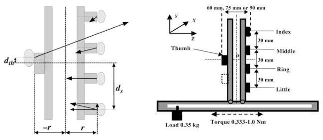
Fig. 1.
Schematic of experimental handle (left panel) and experimental ‘inverted-T’ handle/beam apparatus (right panel). (r moment arm of tangential digit forces, ds projected distance from the center of a finger sensor to the center of thumb center, dth displacement of point of application of thumb force with respect to the center of the thumb sensor.) If displacement of the points of application of finger forces is ignored, moment arms of normal finger forces equal the sum ds+dth. The force components in the z and y directions are called normal and tangential forces, respectively. The black rectangles on the handle represent the sensors. The width of the thumb sensor is 40 mm and the width of the finger sensors is 17 mm. During the experiments, the thumb could be in one of three different locations: the middle position (black rectangle), the bottom position (dotted rectangle), and the upper position (not shown). Subjects were required to maintain the handle in an upright position. The figure is not drawn to scale

