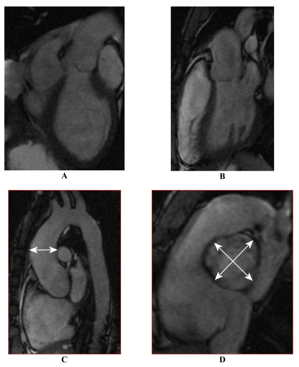
Figure 1.
Structural CMR images used in image analysis: (A) an "LVOT1" orthogonal view centrally in the LVOT, (B) a second orthogonal "LVOT2" view, (C) a "candy-cane" view of aortic arch, and (D) a systolic mid-SOV level view of valve leaflets. Figures (A,B) are used to calculate the aortic channel direction, (C) illustrates AAO size measurement, and (D) illustrates how aortic sizes are measured at the levels of AOV, SOV, and STJ.

