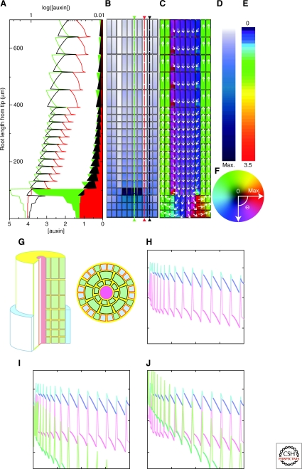
Figure 2.
Models of root transport. (A–F) Model from Grieneisen et al. (Grieneisen et al. 2007) showing that specific static localization of PIN efflux mediators is sufficient to create a reflux loop and generate an auxin peak at the quiescent center. Adapted by permission from Macmillan Publishers Ltd:Nature (Grieneisen et al. 2007), Copyright (2007). (G–J) Model for auxin distribution in the epidermal cell layer by Jones et al. (Jones et al. 2008). Adapted by permission from Macmillan Publishers Ltd.:Nature Cell Biology (Jones et al. 2008), copyright (2008). (G) Visualization of the template used in the simulations. (H–J) Auxin distribution in epidermal cells. Red is nonroot-hair cells and blue is root-hair cells auxin concentrantion for wild-type (H) and aux mutant (I, J) simulations. The difference between (I) and (J) is in the amount of auxin supplied to the tissue.

