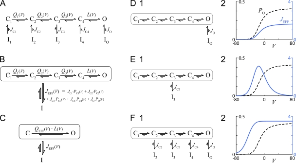
Figure 1.
VDI analysis for detailed, multistate gating diagram. (A) Channel activation involves numerous closed states, with a single open state (top row). Inactivation (bottom row) can occur from any or all of the states in the top row. Equilibrium constants are as shown. (B and C) Simplified but equivalent state diagrams. (D) Behavior of the model in A if inactivation were to proceed exclusively from the open conformation. (D, 2) PO (Eq. 1) and JEFF (Eq. 3) as functions of V (mV). Parameters are as follows: Q1(V) = 40 · exp(0.1 · (V + 10)), Q2(V) = 20 · exp(0.08 · (V − 22.9)), Q3(V) = 10 · exp(0.06 · (V − 21.9)), L(V) = 0.659 · exp(0.001 · (V − 41)), JC1 = JC2 = JC3 = JC4 = 0, and JO = 4. (E) Behavior of the model in A if inactivation were to proceed exclusively from state C3. Format and parameters identical to D, except JC1 = JC2 = JC4 = JO = 0 and JC3 = 12. (F) Behavior of the model in A if inactivation were to proceed equally from states C2, C3, C4, and O. Format and parameters as in D, except JC1 = 0 and JC2 = JC3 = JC4 = JO = 3.5.

