Figure 4.
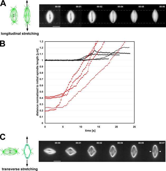
Lateral interactions between microtubules are more robust near the spindle poles. (A and C) The cartoons show the initial positions of the two skewering needle tips within the spindle and the direction of needle movement. (A) The two needles were initially positioned one on each side of the metaphase plate and then spread apart along the interpolar axis. The images show a representative time-lapse series of a spindle being longitudinally stretched. Dashed lines represent the position of the spindle poles before the onset of stretching. (B) Changes in spindle length during longitudinal stretching (normalized to the initial length of the spindle) are plotted versus time, shown as black lines, whereas corresponding plots of needle separation versus time are shown in red. Matching markers indicate data taken from the same experiment. Percentages are the ratio of needle separation at the onset of spindle elongation to the initial spindle length (elongation onset was arbitrarily defined as the time point at which the spindle became 0.5% longer than its initial length). (C) Spindles were also stretched in the orthogonal direction, transverse to their interpolar axes. In these experiments, spindle deformation began at the onset of needle separation and continued until the needles were stopped. White arrowheads indicate the position of the interpolar axis after transverse spindle stretching. Bars, 25 µm.

