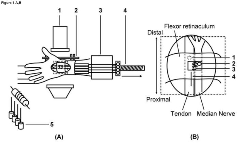
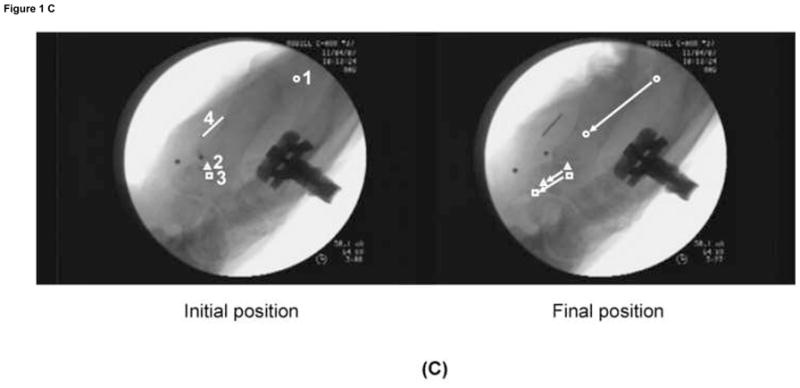
Figure 1. Schematic drawing of the experimental setting.


(A) Experimental setting.
1. Fluoroscopy unit, 2. External fixator, 3. Custom fixture, 4. Actuator, 5. Weight.
(B) Schematic drawing for marker placement.
1. Tendon, 2. Median Nerve, 3. SSCT, 4. Ruler.
(C) Displacement of each marker for the Flex 60 position.
1. Tendon, 2. Median Nerve, 3. SSCT, 4. Ruler.
