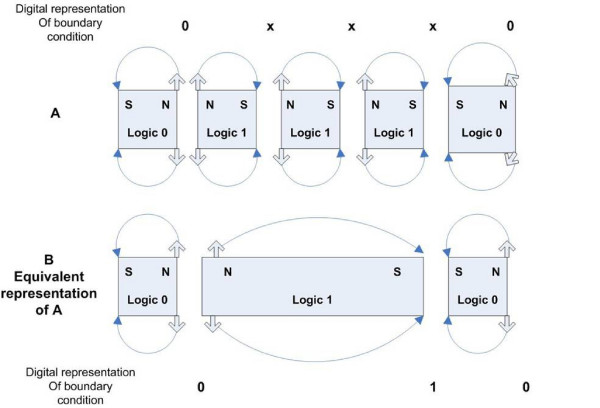
Figure 2.
Magnetic Boundary Condition. In general, allowing a magnetic region to represent a logical "1" if magnetized N-S and a logical "0" if magnetized S-N results in a non orthogonal detection of flux transitions by the read head. Figure A shows that the intended pattern of bits "0 1 1 1 0" is not detected by the read head. Figure B shows the equivalent magnetic region layout which yields the detected bit pattern of "0 1 0."

