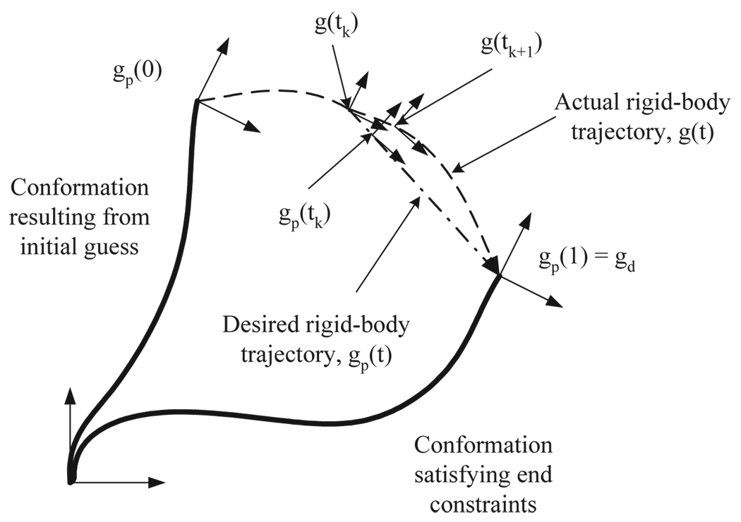
Figure 1.
Schematic diagram explaining the concept of rigid-body trajectory. gp(0) is the position and orientation of the distal end in the conformation resulting from the initial guess, and gp(1) should be the desired one of the distal end, i.e., gp(1) = gd. At time tk, gp(t) forms the geodesic from the current frame, g(tk), to gd.

