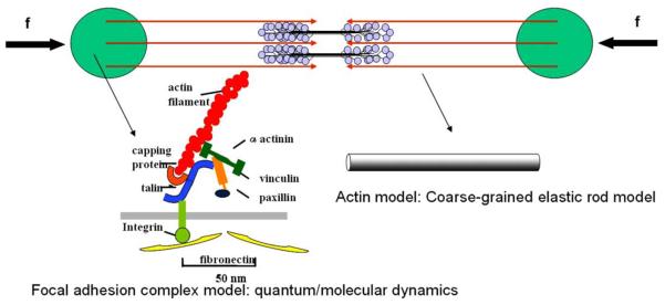
Fig. 23.
A schematic figure of the actomyosin-focal adhesion model. Each actin filament is illustrated as an arrow and its polarity is indicated. The two circular areas represent the focal adhesion sites. The double headed myosin-II motors are assembled into bipolar ‘mini-filaments’ that connect actin-filaments of opposite polarities. The focal adhesion complex will be modeled by quantum or molecular dynamic simulations. The actin filaments will be modeled as coarse-grained elastic rods. The contractile force will be applied onto the focal adhesion complex via atomistic–continuum coupling methods.

