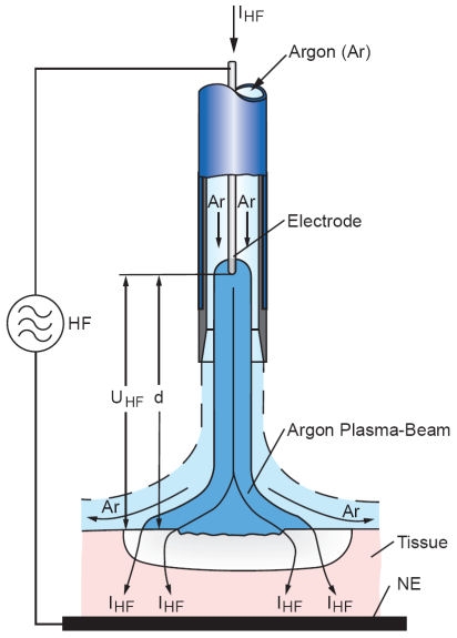
Figure 3. Schematic representation of a typical APC setup. The argon flows through a tube containing the electrode wire. The discharge is ignited by a HF voltage UHF between the wire end and the tissue. After breakdown, HF current IHF flows into the tissue, causing a coagulation effect, and back to the HF generator through the neutral electrode (NE).

