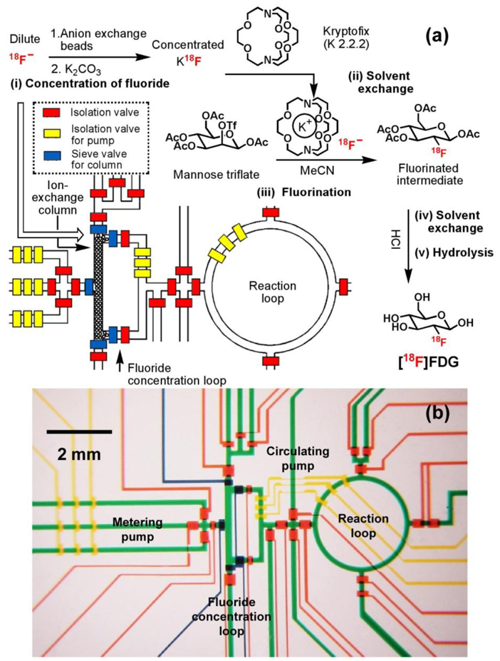
Figure 3.
(a) Schematic representation of a PDMS-based microfluidic reactor used in the production of 2-deoxy-2-fluoro-D-glucose ([18F]FDG). Five sequential chemical processes produced nanogram (ng)-level of [18F]FDG. The operation of the device is controlled by pressure-driven valves, with their delegate responsibilities illustrated by their colors: red for isolation valves, yellow for isolation valves for pumping, and blue for sieve valves (for trapping anion exchange beads in the column module). (b) Optical micrograph of the central area of the microreactor. Various channels have been loaded with food dyes to help visualize different components of the microfluidic chip: colors as in (a), plus green for fluidic channels.

