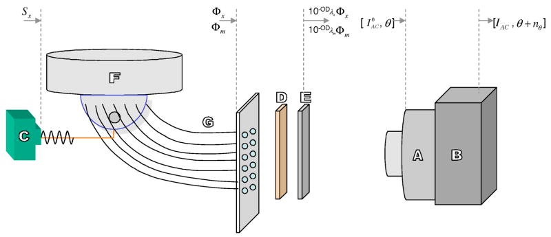
Fig. 3.
Schematic of the experimental setup. The various components are labeled to describe: (A) a gain-modulated image intensifier, (B) a 16-bit cooled CCD camera, (C) a modulated laser diode used as a light source, (D) an 830-nm band pass filter, (E) a holographic notch filter, (F) the breast shaped phantom, and (G) the detector fibers leading to an interfacing plate. The Fig. is not to scale.

