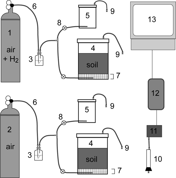
FIG. 1.

Schematic representation of the soil microcosm setup (not to scale). The experimental set up consisted of two gas cylinders (no. 1 and 2), each connected to a humidifier (no. 3), the 1-liter soil microcosm jar (no. 4), and an empty 250-ml jar (no. 5). Gas from the cylinders could flow through the humidifier and into the jars via Tygon tubing (no. 6). A plastic fine-mesh screen was positioned 2 cm above the gas inlet in the 1-liter soil microcosm (no. 7), to allow the gas from the inlet to expand evenly across the bottom of the jar before flowing through the sieved soil. The 250-ml jars (no. 5) remained empty of objects and soil during the experiments, and gas was prevented from going from the T-intersection to the smaller jar during most of the experiments by a clamp (no. 8). The gas line was directed through the empty jar once a day to measure the H2 concentration in the inlet gas line. The outlet from the lids, consisting of Tygon tubing and luer fittings (no. 9), could be connected via a column filled with magnesium perchlorate desiccant (no. 10) to an H2 sensor (no. 11). H2 readings were collected via a data logger (no. 12) and saved onto a computer (no. 13).
