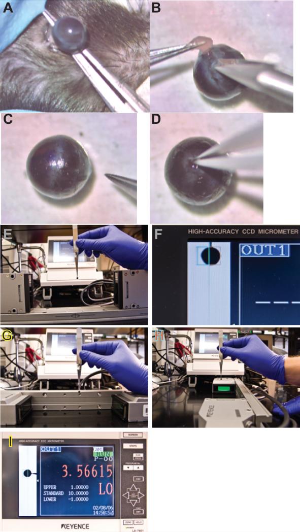
Figure 3.
Video of the dissection and measurement techniques. Video 3A presents the dissection, and Video 3B illustrates the measurement technique. Representative images at different stages of the dissection and measurement process are illustrated in the static images in Figure 3. Panel A, removal of the eye; Panel B, removal of fat and extraocular muscle; Panel C, a representative eye following removal of fat and muscle and the optic nerve (note the orientation ink mark on the cornea identifying superior); Panel D, grasping the remnant of the optic nerve with forceps; Panel E, measurement of the A-P dimension; Panel F, re-orienting the micrometer heads and rail; Panel G, measurement of the N-T dimension (note the position of the #7 forceps handle and the ink mark indicating superior); Panel H, turning the mouse eye 90 degrees to measure the S-I axis (note the orientation of the #7 forceps handle relative to the ink mark on the superior point of the cornea and the centering coordinates on the laser micrometer rail).

