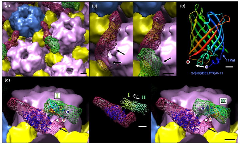
Fig. 8.

Close-up views of the UL25-GFP density. (a) Subunit boundaries have been estimated and colored as for Figure 7 with UL25 and GFP densities shown as a red and a green mesh, respectively. Bar = 20Å. (b) An alternative view revealing contacts between a hexon and the CCSC density (with GFP removed to aid visibility), at left, and the GFP density, at right. Bar = 20Å. (c) Ribbons representation of the GFP atomic model with termini and amino acid 11 (valine) marked, along with the sequence of GFP amino acids 2-11 (below). When inserted into UL25, the N- and C-terminus of GFP may be closer together, possibly by refolding the N-terminal 11 amino acids moving the N-terminus as indicated (white arrow). Bar = 5Å. (d) Atomic models for UL25 (PDB ID: 2F5U – dark blue ribbons) and GFP (PDB ID: 1EMA rainbow and green ribbons) positioned within the cryoEM density. The UL25 atomic model (residues 134-580) is positioned so that the missing N-terminal 133 residues would occupy the distal region (black arrow) where contact with GFP appears most likely. The GFP model may be placed in two non-overlapping orientations to fill the green mesh, as indicated at left (position I) and at right (position II). These locations place the termini midway along the GFP density that closely approaches the CCSC density (arrowhead). Bar = 20Å. The inset shows the two GFP positions, represented by light and dark green models, superimposed on the CCSC density. The C-termini of the GFP are placed in the GFP density where it most closely approaches the UL25 density (arrowhead).
