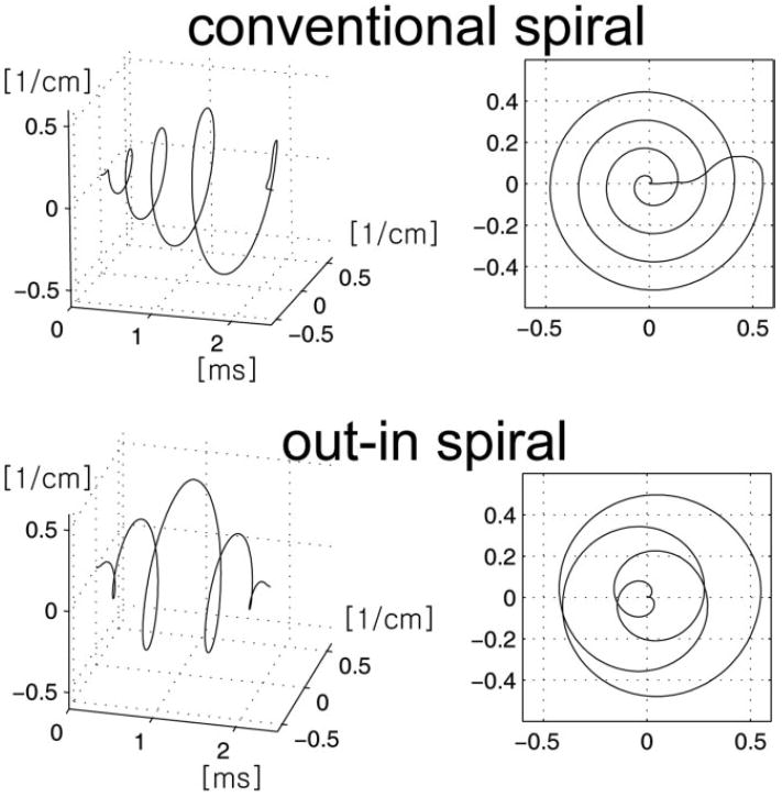
FIG. 2.

Illustrative example of the conventional spiral (top row) and out–in spiral (bottom row) used in MRSI. The left column shows spiral trajectory as a function of time, while the right column shows the projected trajectory on to the kxy plane. In MRSI, spiral lobes are repeatedly played out during a readout; therefore, each spiral lobe ends at the kx = ky = 0 position. This is achieved using rewinders for the conventional spiral, while for the out–in spiral the symmetry of the gradients played out naturally returns the trajectory back to origin.
