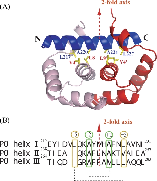
FIGURE 3.
Interactions between P0 spine helix and P1 dimer. A, close-up view of P0 spine helix I (blue) and first P1 dimer (pink/red). The hydrophobic residues important for binding are shown as sticks. The 2-fold axis of the P1 dimer is shown as a red broken line. B, the sequences of three spine helices. The hydrophobic residues important for the binding of P1 dimers are marked in green and orange boxes. They are positioned at ±2 and ±5 from the 2-fold dimer axis.

