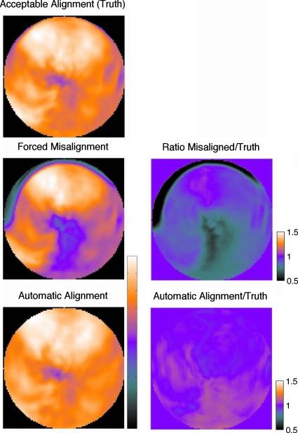
Figure 7.
Polar maps for a patient combination 1 showing the AC PET data with originally aligned map, after forced misalignment (row 2), and after proposed alignment (row 3). Ratio maps in the second column show that forced misalignment causes a clear AC artifact. After proposed alignment, there are no AC artifacts. In the first column, each polar map has its color range scaled to its maximum value to correspond to clinical qualitative presentation of a polar map.

