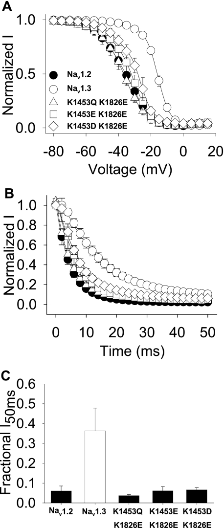
FIGURE 8.
Complementary carboxyl-terminal and domain III-IV linker mutants. A, voltage dependence of inactivation is shown for Nav1.3 K1453Q/K1826E (triangles), Nav1.3 K1453E/K1826E (squares), and Nav1.3 K1453D/K1826E (diamonds) double mutants and wild-type Nav1.2 (black circles) and Nav1.3 (white circles) channels. The parameters of the fits and sample sizes are shown in Table 4. B, normalized current versus the depolarization time is shown for entry into inactivation, as described under “Experimental Procedures.” The parameters of the fits and sample sizes are shown in Table 4. C, fraction of inactivating current at the 50 ms time point during a depolarization to −10 mV is plotted for the mutant and wild-type channels. The fraction of the inactivating current was determined as the averaged current during 1 ms at the midpoint of the trace divided by the peak current. Sample sizes were 9 for Nav1.2, 8 for Nav1.3, 5 for Nav1.3 K1453Q/K1826E, 5 for Nav1.3 K1453E/K1826E, and 6 for Nav1.3 K1453D/K1826E. Data points indicate means, and error bars show S.D. values.

