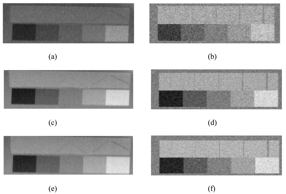
Figure 11.
The physical and the mathematical phantom images: (a) measured 30kVp, 80mA; (b) simulated 30kVp, 80mA; (c) measured 35kVp, 100mA; (d) simulated 35kVp, 100mA; (e) measured 40kVp, 64mA; (f) simulated 40kVp, 64mA. The nylon fibres in the mathematical phantom were simulated having the same diameters as those in the physical phantom, but in a vertical rather than diagonal direction for ease of implementation.

