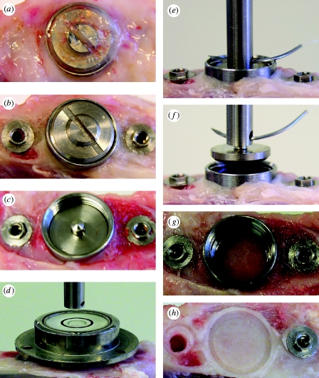
Figure 3.
Measurement of bonding force. (a–c) The overgrown tissue and cover screw were removed. (d–f) The disc implant was aligned to the central axis of the load cell using the level tube and then coupled to the load cell by means of a pin and pinhole connection. Note (g) no leakage of newly formed bone into the bevel connection between the disc implant and the housing and (h) the newly formed bone underneath the disc IS, showing the replica shape of the cylindrical lip and the offset.

