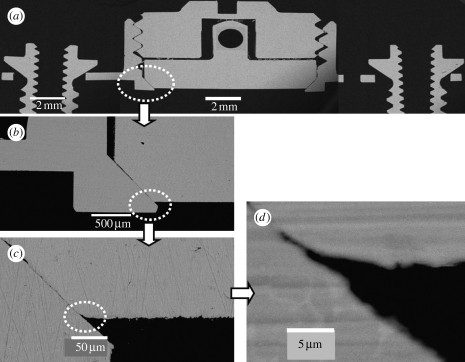
Figure 4.
SEM cross-section view. SEM cross-section observations of the TBS assembly embedded in resin. Note that the disc implant has the functional flat surface with the bevelled flange at the bottom and the cylindrical pin with a hole at the top for connection to the load transducer. (a) The disc implant is positioned in the bevel seat of the housing chamber by fastening the cover screw, the contact between the disc implant and the cover screw is only through the conical apex of the cylindrical transducer of the disc implant. Scale bar, 2 mm. (b) Bevel connection between the bevelled flange of the disc implant and the bevel seat of the housing, 500 μm long. The cylindrical lip of the housing is approximately 70 μm of the inner height and 400 μm of the outer height. Scale bar, 500 μm. Note the clearance between the vertical walls of the disc implant and the housing chamber, a gap of approximately 80 μm, ensuring no occurrence of friction during pull-off movement of the disc implant. (c) Bevel offset, approximately 50 μm. Scale bar, 50 μm. (d) High magnification of the titanium-to-titanium bevel seat fitting shows a leak-tight connection, with a gap of less than 1 μm. Scale bar, 5 μm.

