
Figure 2.
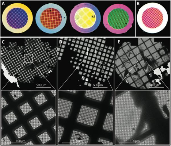
A visual characterization of Cryomesh grids. A) Cryomesh grids as imaged under standard fluorescent lighting with the ceramic silicon layer on the side of the grid facing the viewer. The colors of the grids are related to the thickness of this film layer (see Figure 1) and extend over the outside support ring since the film layer is above the support layer when viewed from this side. B) Another Cryomesh grid that has been flipped over so that the film layer is facing away from the viewer and is on the other side of the support layer. In this case, the outside support ring now has neutral, rather than colored appearance. The outside support ring of all of the grids in panel A would have a similar appearance if they were flipped over. C,D,E) low magnification (49X) and higher magnification (500x) images of different Cryomesh grids with different mesh sizes. All have samples preserved in vitreous ice. Most interesting is the grid in panel E, which has a very large mesh size, with each square containing thousands of holes and even ice distribution.