
Figure 6.
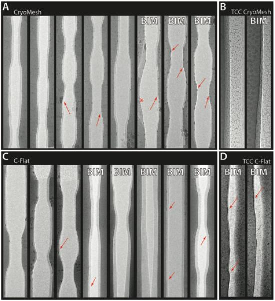
A gallery of channels that have been cut through the ice layers on different grid types. For the images in panels A and C, 45° and 0° images of the same area were aligned so that the thickness and variations in the ice layer could be easily observed. Further details can be found in Methods 2.4. A) Cryomesh grids B) carbon-coated Cryomesh C) C-Flat and D) carbon-coated C-Flat. Areas with subtle thinning or curvatures in the ice are denoted with red arrows. The red asterisk marks locations where the bilateral symmetry has been broken, likely due to ice movement. Channels that belong to images that exhibited BIM are marked by an upper-case ‘BIM’. Note that overall, the Cryomesh ice is more regular in flatness and thickness than the C-Flat ice. Also note that additional carbon film makes ice more irregular in thickness, and even more in flatness. The thin carbon coating also allows one to visualize the channel thickness without having to align the 0° images with the 45° images (though we did this anyways to confirm what we saw). Presumably this is because the ice/carbon interface creates contrast in addition to the ice/vacuum interface.