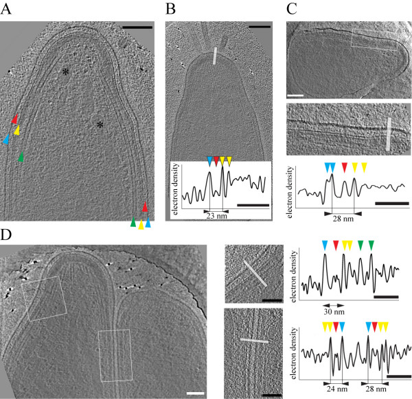
Figure 2.
Topology of the supra-alveolar space of Plasmodium berghei sporozoites. A. A 10 nm thick slice through a tomographic reconstruction of the apical end of the sporozoite. Arrowheads indicate the plasma membrane (blue), the supra-alveolar space (red), the IMC (yellow) and microtubules (green). Two micronemes are indicated by asterisks. Note the electron dense cap that constitutes the polar ring (highlighted pink in Figure 3). Scale bar: 100 nm. B. A 10 nm thick slice through a tomogram of a different sporozoite. Scale bar: 100 nm. Graph depicts the electron density profile along the white bar. Arrowheads indicate the peaks corresponding to the plasma membrane (blue), material in the supra-alveolar space (red) and the membranes of the IMC (yellow). Scale bar: 50 nm. C. A 10 nm thick slice through the apical end of a different sporozoite showing a larger plasma membrane to IMC distance as the one in B. Scale bars: 100 nm for the micrograph, 50 nm for the electron density profile. D. A 10 nm thick section through a tomogram of a sporozoite that folds back on itself within a hole of the EM grid thus showing the apical and the rear end of the same parasite. White square and rectangle are enlarged to the right. The bars indicate the areas from which the electron density profiles were obtained. Peaks are indicated as in panel B with green arrowheads additionally pointing to the densities corresponding to microtubule walls. Note the different distances between the plasma membrane and the IMC as indicated. Scale bars: 100 nm for the micrographs, 50 nm for the electron density profiles.

