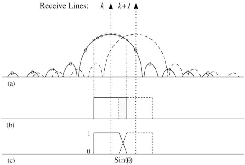
Fig. 2.

(a) Directivity patterns of the received coded wavefronts associated with the kth (solid) and (k + 1)th (dash) receive lines; “○” and “*”: image directions for constructing the augmented G; “*”: image directions for filtering, (b) filtering block regions associated with receive image line k (solid) and k + 1 (dash); shaded area: the overlapping region, and (c) the weighting function for compounding two neighboring filtering block regions.
