
Fig. 1.
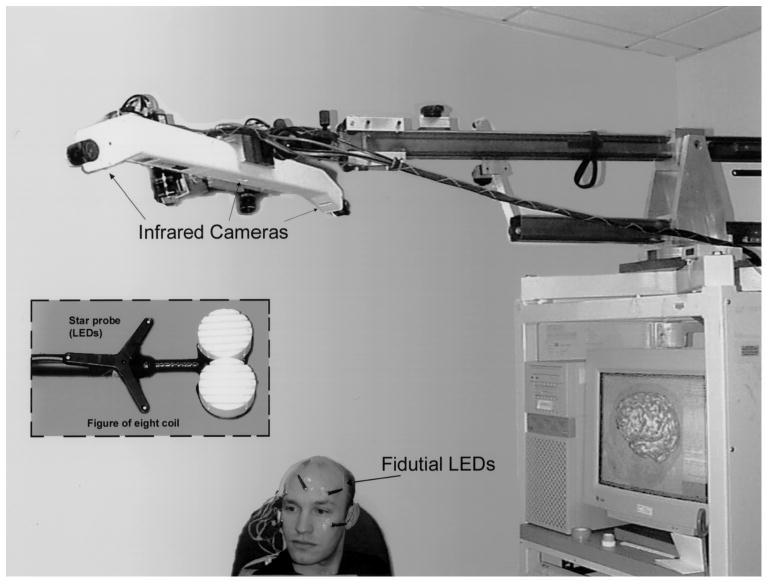
Diagram of experimental setup used for guided focal TMS. The volunteer is shown with LEDs fixed to the maxillary and forehead regions. Light flashes emitted by the LEDs, which serve as fiducials, are registered by the infrared cameras above. The star probe attached to the figure of 8 coil also has LEDs for determining the relative position of the stimulating coil to the scalp. Both the pixsys system (i.e. optical tracking system) and laser scanner used for the initial coregistration are attached to the boom overlying the volunteer's head.