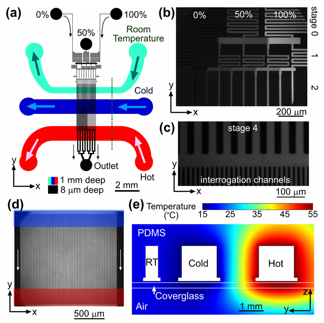
Figure 1.
Microfluidic device. (a) A schematic drawing of the microfluidic device. The flow channel network is shown in black. Three inlets of the device are labeled by the relative concentrations of the solutions fed to them, 0, 50, and 100%. The cyan, blue, and red channels (all 1 mm deep) are for circulation of room temperature, cold, and hot water, respectively. Arrows indicate flow directions. (b)–(d) Fluorescence micrographs of different parts of the gradient generator taken with 0, 25, and 50 ppm solutions of fluorescein in a pH 7.5 phosphate buffer fed to the 0, 50, and 100% inlets of the device, respectively. (b) Mixing channels of stages 0 – 2 and redistribution channels (horizontal strips) between them. (c) Mixing channels of stage 4 (25 µm wide straight channels with 25 µm partitions), a redistribution channel (horizontal strip), and entrance parts of the interrogation channels (8 µm wide with 8 µm partitions). (d) Interrogation area of the device with 100 parallel channels (vertical strips). Locations of the cold and hot circulation channel are marked by a blue and red horizontal strip, respectively. (e) Cross-sectional view of the microfluidic device along the dotted line in (a) with color-coded temperature profile as obtained from a two-dimensional FEMLAB thermal conductivity simulation with the boundaries of the cold, room temperature (RT), and hot channels, at 15, 20, and 55 °C, respectively (see Supporting Information, Figure S1 for further details).

