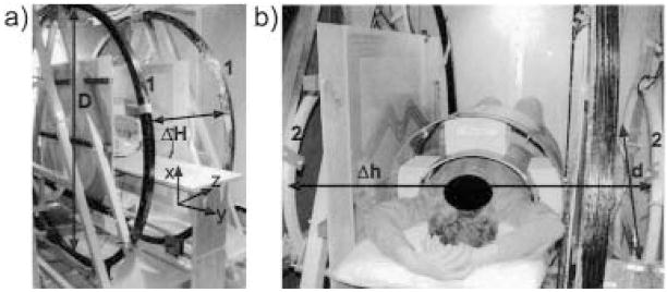
Figure 2.
Photographs of the very-low-field open-access human MRI magnet system showing the placement of the B0 coils: a) Large B0 coils, labeled “1,” with diameter D = 2 m, separation ΔH = 0.74 m. Lab frame coordinates are included in this photograph. b) Small coils, labeled “2,” with diameter d = 0.86 m, separation Δh = 1.2 m. Human subject is shown in the horizontal imaging position.

