
Figure 1.
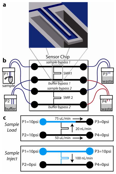
Suspended microchannel resonator (SMR) system schematic. (a) Cut-away view of SMR microcantilever. The U-shaped sensor channel has a 3 × 8 μm cross section and is embedded in a resonating silicon beam extending 200 μm into a vacuum packaged cavity. (b) Sensor chip with 2 SMRs addressable by bypass channels connected by Teflon tubing to pressure-controlled vials off-chip; one SMR is used as a control (reference) sensor. Blue tubing: ID 225 μm, red tubing: ID 150 μm. (c) Fluid delivery schemes: Sample Load fills sample bypass channels with sample (blue) while the microcantilevers and buffer bypasses are flushed with running buffer (black), Sample Inject delivers a sharp concentration sample to the microcantilevers. Figures not to scale.