
Fig. 2.
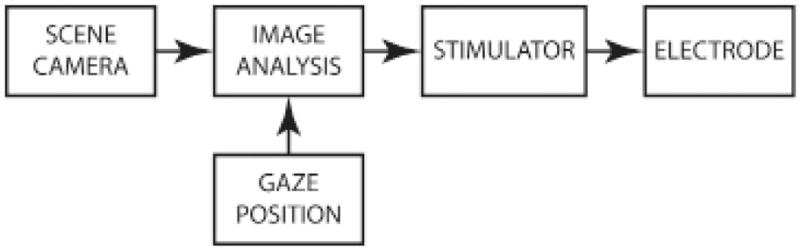
Block diagram of a visual prosthesis. Information flows left to right in this diagram depicting the basic steps in converting a visual scene into patterned stimulation of neural tissue in a visual prosthesis. In contemporary designs, the scene camera, gaze position measurement, and image analysis are external to the body, and wirelessly communicate to chronically implanted multichannel stimulators and multicontact electrodes. Designs that retain the eye as an imaging apparatus do not require gaze position measurement to compensate camera images for movement of the eyes (see main text for discussion of gaze compensation).