
Fig. 1.
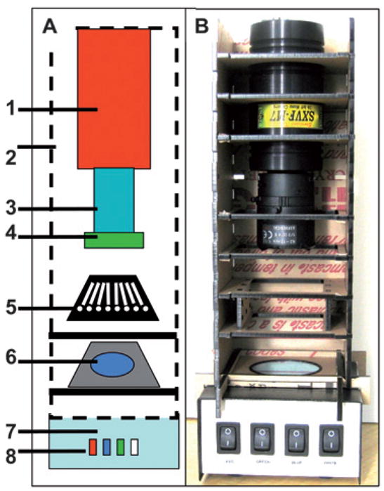
LED-CCD multi-wavelength detector. A schematic configuration of the multi-wavelength LED detector (A), photograph of the detector (B). The elements in the schematic and the photograph of the actual detection platform are: SXVF-M7 CCD camera (1) mounted in a homemade acrylic shelf box (2), which was designed to hold the filters and the sample chips. The camera is equipped with a Tamron manual zoom CCTV 4–12 mm, f1.2 C-mount lens (3) with a green pass band emission filter (4) mounted on the end of the lens. The 8-channel LOC (5) is placed on a shelf in the camera box above the blue band pass excitation filter (6). The camera shelf box is placed on the top of the multi-wavelength LED illuminator (7) with light switches to operate the red, blue, green and white LEDs (8).