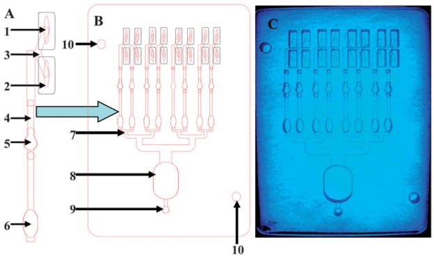
Fig. 2.
Functional elements of multi-channel LOC system. An expanded single channel (A) where the sample reservoir (1) and the reagent reservoir (2) are joined via V junction (3) to the joining channel (4). The cleavage reaction is monitored in the detection wells (5) designed with air traps to minimize air bubbles, followed by a mixing trap (6). The full schematic of eight-channel LOC chip (B), including the eight channel negative pressure distribution splitter (7) connected to a waste chamber (8) to the outlet for a pump or syringe (9). The alignment holes (10) were designed to simplify fabrication. A clear PMMA LOC device (C) photographed with blue illumination to increase contrast.

