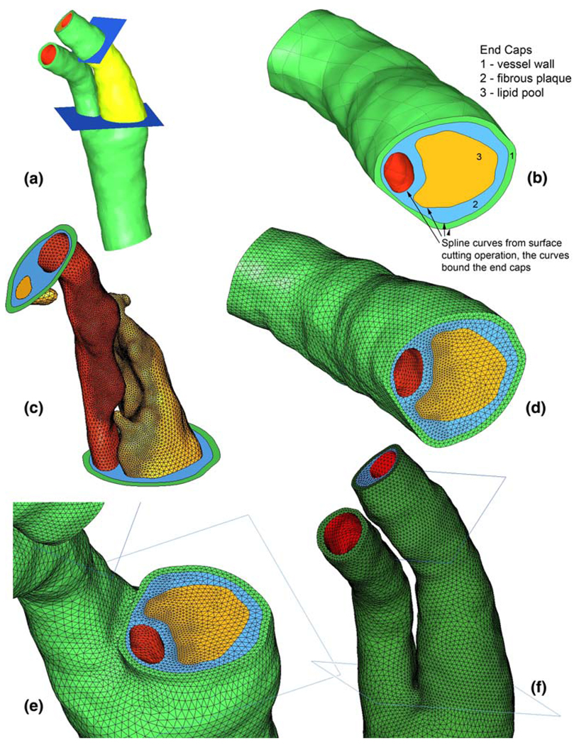
Fig. 2.
a IGES surfaces for diseased carotid bifurcation and truncation planes (region of interest rendered in bright yellow-green). b Bottom aspect of region of interest after cutting of surfaces with truncation planes, end caps made from spline curves. c Surface meshing for fine-mesh model. d End cap meshes generated due to forced division of spline curves. e Coarse mesh shown at bottom truncation plane. f Full coarse mesh shown at level of bifurcation and above (for all figures, green vessel wall, blue fibrous plaque, yellow lipid, red lumen surface)

