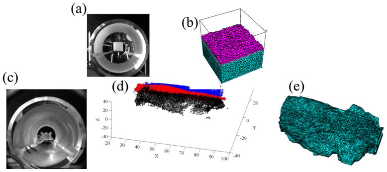
Fig. 6.
(a) photograph of the cubic phantom taken by the EMCCD camera when the phantom was placed in the conical mirror; (b) 3D mesh for cubic phantom; (c) photograph of the mouse taken by EMCCD camera when the mouse was placed in the conical mirror; (d) extracted surface plots of the mouse, where different color points were obtained from different line pattern lasers illuminating different surfaces; (e) final 3D mesh of the mouse surface geometry.

