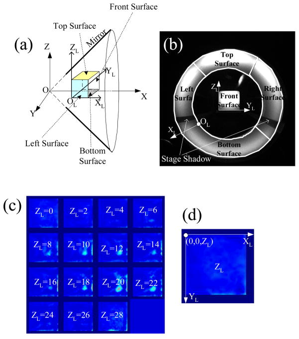
Fig. 9.
Definition of coordinate systems for phantom experiment. (a) The conical mirror coordinate system (X, Y, Z) and the local coordinate system of cubic phantom (XL, YL, ZL). (b) The local coordinate system viewed in the CCD measurement picture. (c) To view the reconstructed image in detail, the sections at different ZL are shown. (d) The coordinates of each plotted section.

