Fig. 4.

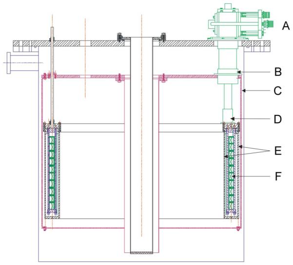
Schematic drawing of a cross section view of the magnet in its cryostat. A: cryocooler, B: the first stage of cryocooler, C: radiation shield, D: the second stage of cryocooler, E: annular can for solid nitrogen, F: coils.

Schematic drawing of a cross section view of the magnet in its cryostat. A: cryocooler, B: the first stage of cryocooler, C: radiation shield, D: the second stage of cryocooler, E: annular can for solid nitrogen, F: coils.