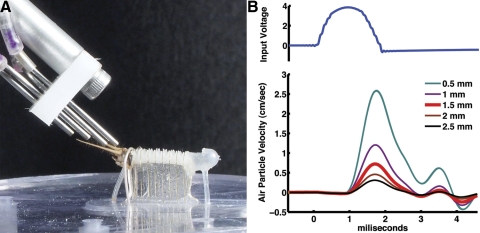
Fig. 1.
Multinozzle air-current stimulus device. A: photograph of the multinozzle stimulus device, positioned over a cricket cercus as in the actual experimental preparations. B: plot of the air currents generated through a single nozzle, recorded with the MicroFlown positioned at 5 different distances from the nozzle tip. The top trace is the voltage signal sent to the minispeaker connected to the nozzle and the bottom 5 traces are plots of air current velocity vs. time at the different indicated distances between the nozzle tip and MicroFlown sensor.

