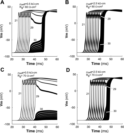
Fig. 8.
Conduction along inhomogeneous fibers with different combinations of Rg and ρoeff. A: conduction delay when Rg(PC) in the first half of the fiber was increased from to 1.5 to 60 Ω-cm. B: reduced conduction delay when ρoeff was also increased from 0.50 to 2.5 kΩ-cm. C: conduction block when Rg(PC) was increased from to 1.5 to 70 Ω-cm. D: restored conduction when ρoeff was also increased from 0.50 to 2.5 kΩ-cm. The numbers shown (21, 29, and 30) indicate the cell number. Vm, membrane voltage.

