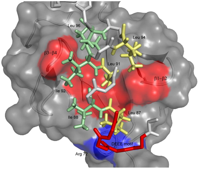
Figure 2. Structure diagram of UIM-Ubiquitin interactions.
UIM binding is accommodated by a continuous hydrophobic patch on ubiquitin's solvent-exposed surface, formed by residues L8, V70, I44 and A56 shown in red from left to right in the structure. The UIM uses hydrophobic residues on two sides of the helical structure (shown as yellow and green sticks respectively) to engage the clamp-like surface on ubiquitin. Additional stabilizing electrostatic interactions are formed between the UIM n-terminal DEEE motif (red) and R42 and R72 on ubiquitin's β3 strand and C-terminus (blue surface).

