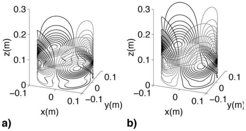
Figure 2.

The upper half (z > 0) of the X2–Y2 wire pattern given by (a) minimum inductance and (b) minimum power methods. The bottom halves of the coils are mirror images of the top halves not shown in this figure. Minimum inductance designs tend to give more complex wire and more compact wire patterns than minimum power designs.
