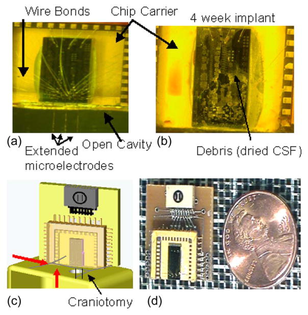
Fig. 2.
Micrographs of our bio-MEMS device. (a) Clean device before implantation, with three movable microelectrodes extending off the edge of the chip. The chip is 3 mm by 6 mm, and it is wire bonded to a chip carrier with a glass-cap package. (b) Micrograph of a device that was implanted for a period of four weeks without any protective layer. Fluid entry and the debris left behind after dehydration are clearly evident, which prevented movement of the microelectrodes. (c) Schematic of the implanted device resting on the skull, with the microelectrodes extending through the craniotomy. The red arrows show fluid entry either via the craniotomy or the exudates from the skin incision surrounding the craniotomy. (d) Micrograph of a packaged device next to a U.S. penny.

