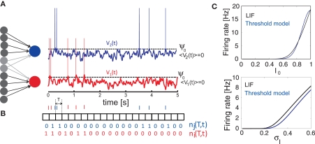
Figure 1.
Generation of spike trains and transformation to spike counts. (A) Generation of spike trains from correlated voltage traces of two neurons with common presynaptic partners. (B) Red and blue vertical bars indicate the spike trains of two neurons. Squares show the boundaries of bins with duration T. ni(T,t) and nj(T,t) illustrate corresponding binned spike trains. (C) Firing rate vs. input current in the LIF model (first order solution) and the threshold model (Eq. 11) computed for σI = 0.25 (top), I0 = 0.6 (bottom) and ψ0 = 1, Vr = 0, τM = 15 ms and τI = 5 ms.

