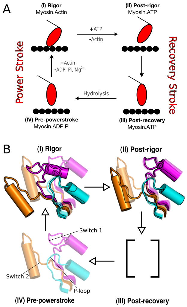
FIG. 1.
The Lymn-Taylor cycle. Figure (A) shows the functional details of the cycle; Figure (B) shows the position of the switches for each state. (I) Rigor state - both switch I and switch II are open; no ligand. (II) Post-rigor state - switch I closed, switch II open; ATP. (III) Post-recovery state - switch I closed, switch II closed; ATP. (IV) Pre-powerstroke state - both switches are closed; ADP.Pi. The post-recovery state is assumed to have the same lever arm position as in pre-powerstroke, but ATP has not been hydrolyzed yet; it is in equilibrium with the post-rigor state (no structure is available but see Ref. [45]).

