Figure 1.
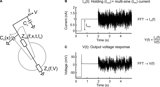
Circuit diagram and multi-sine measurement procedure. (A) Equivalent circuit diagram of a sharp electrode inside a neuron. The neuron is described as a frequency- and voltage-dependent impedance, Zn(f, V); the electrode is described as a frequency-, depth-, time- and current-dependent impedance Zee(f, x, t, Ie) serial to and a depth-dependent capacitance Ce(x) parallel to the neuron; additional constant parallel stray capacitance Cs of amplifier circuit. (B,C) Multi-sine current stimulus with discrete frequencies superimposed on a constant holding current, Ihold (B), injected through the electrode leading to a voltage response (C). Transformation into the frequency-domain by a fast Fourier transform (FFT) and division of the stimulus current by the voltage response leads to the admittance transfer function, Y(f).

