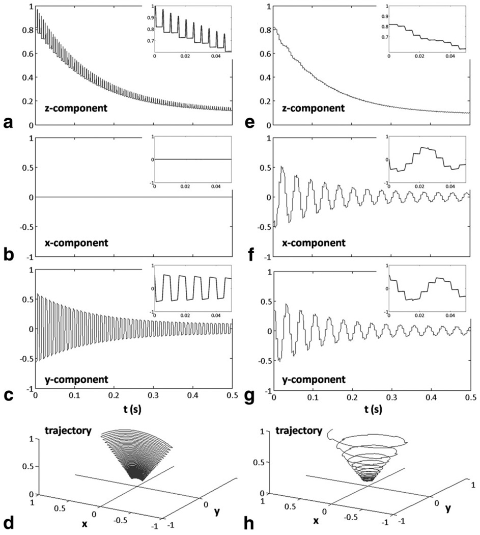
FIG. 2.
Longitudinal (a,e) and transverse (b,c,f,g) components and magnetization trajectory (d,h) during slSSFP (right) and comparison to bSSFP (left). The simulation depicts a magnetization trajectory in a frame of reference rotating at the Larmor frequency and so the magnetization rotates in the transverse plane during spin-lock (f,g) as shown by oscillating x and y transverse components. The bSSFP flip angle α is twice the slSSFP angle of effective field orientation.

